astviewer?astviewer python script visualises the contents of a
FrameSet object created by the starlink AST library (see
www.starlink.ac.uk/ast). It allows you to:
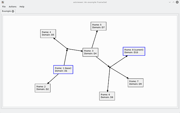
Below is an example of how a FrameSet is displayed. This is the
demonstration FrameSet that is displayed if no astviewer is
started without specifying an input file on the command line:
astShow
method within AST. It is also the format used by the Starlink ATOOLS
package. The text file may contain the dump of a FrameSet, a Mapping, or
a Frame. However, if a Mapping or Frame is supplied, the main
astviewer
window that normally displays the FrameSet will remain blank, and the
Mapping or Frame will be displayed in a pop-up dialog.
astviewer is included in the Starlink ATOOLS package, which
is part of the Starlink Software Collection (see www.starlink.ac.uk).
It can also be obtained from pypi.org - search for project
'astviewer'. To install it, do:
% pip install starlink-astviewer
astviewer requires the following packages to be
installed:
pyqt4 library. This is usually included in Linux
distributions, but can be installed separately if required. See
http://pyqt.sourceforge.net/Docs/PyQt4/installation.html.
pyast package - a Python interface to AST.
This can be installed from pypi.org by doing:
% pip install starlink-pyastDocumentation is available at
timj.github.io/starlink-pyast/pyast.html.
Note, pyast version 3.11 or later is required for full functionality.
STARLINK\_DIR. If the SSC is not available,
astviewer will still run but will not be able to read FrameSets from NDFs.
io.fits
module within astropy (see www.astropy.org)
must be available. If the astropy.io.fits is not available,
astviewer will still run but will not be able to read FrameSets from FITS
files.
astviewerastviewer as follows:
% atools
% astviewer
If you have installed astviewer from www.pypi
you need to determine where the script has been installed. If you ran
pip install with the --user option, it will
probably be in $HOME/.local/bin, so for convenience you
should either add this directory to your PATH or define an alias to run
astviewer. It can then be run as:
% astviewer
In either case, if an input file is specified on the command line a
FrameSet will be read from the file and displayed. If no input file is
specified, an example FrameSet will be generated and displayed
automatically. To replace this example FrameSet, use the Open
option in the File menu to read a FrameSet from a selected
file (see 'Data formats'). In either case, the
FrameSet can be explored as described in 'The
FrameSet viewer'.
To close down astviewer, use the Close item in
the File menu on the main window, or press Control+Q.
Frames: Each box represents a coordinate Frame, and displays its main properties:
ctrl-Cctrl-B.
Clicking and dragging a Frame will move the Frame icon, together with any connected Mappings and child frames (i.e. any Frames reached by out-going arrows from the selected Frame).
Clicking on a Frame whilst the control key is pressed and
then dragging will draw out a red dotted arrow. If the mouse button is
then released with the pointer over another Frame, the Mapping between
the two Frames will be displayed in a pop-window - see
Viewing the details of a Mapping.
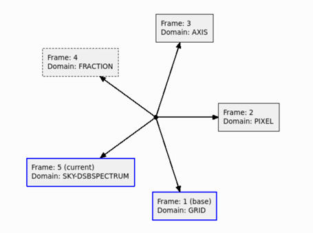
Mappings: Each arrow represents a Mapping, containing two transformations - the forward transformation of a Mapping transforms positions in the direction of the arrow, the inverse transformation transforms positions in the opposite direction. Each end of a Mapping can be connected to a Frame (a box) or a Node (a black dot). A Node can be thought of as an anonymous intermediate coordinate system for which no metadata has been stored.
Clicking on a Mapping arrow will create a pop-up window containing more extensive
details of the Mapping - see
Viewing the details of a Mapping. Details of
the Mapping from the base Frame to the current Frame can be viewed by pressing
ctrl-M.
The Mapping between any pair of Frames can be seen by clicking and
dragging between the Frames, with the control key pressed.
The File menu: contains the following:
astviewer behaves. Currently, the only option that can be
set is the FitsChan attribute settings to be used when
reading a FrameSet from a FITS file or text file containing FITS headers.
The Actions menu: provides the following actions that
be applied to the displayed FrameSet:
Get button to display the
current value of the attribute. Whether this is the default value, or a
value that has been set explicitly will be indicated by the string
'(default)' or '(set)' appended to the end of the attribute value.
Alternatively, press the Clear button to
first clear the attribute and then display the default value of the
attribute. Pressing the Return key in the text box is like
pressing the Get button.
astSimplify
method to the FrameSet. The simplified FrameSet is displayed in a new tab.
Actions menu. An example SkyFrame is shown below:
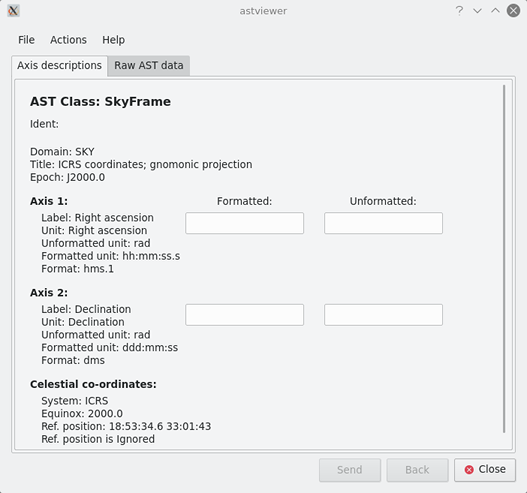
Viewing the raw AST data: Click on the "Raw AST data" tab to see a
full description of the Frame in the form created by the AST
astDump method.
Axis descriptions: The "Axis descriptions" tab contains a human-friendly summary of the main details of the Frame. First the properties of each individual axis are listed, followed by properties of the celestial, spectral or time coordinate systems to which the axes relate.
Formatting and unformatting axis values: Some classes of Frame format numerical axis values in a specic way. For instance, the SkyFrame class uses numerical longitude and latitude values in units of radians internally, but can formatted them as (for instance) sexagesimal strings for human readers. The TimeFrame class can similarly format axis values as ISO date strings. Entering a numerical value into an "Unformatted" text box and then pressing return (or shifting focus to another box) will cause the corresponding formatted string to appear in the "Formatted" text box. Likewise, entering a formatted string into a "Formatted" text box and then pressing return (or shifting focus to another box) will cause the corresponding numerical value to appear in the "Unformatted" text box.
The File menu: allows the Frame to be saved to a
text file in AST "raw" format.
The Actions menu: allows Frame attribute values to
be displayed, cleared or changed. Note, any changes made to the
attributes of the Frame will be lost when the Frame pop-up window is
closed.
The Back button: is disabled unless the Frame details
were displayed as a result of clicking on a link within a previously
displayed Mapping (see Viewing the details of a
Mapping). If clicked, the Frame details will be replaced by the
details of the previously displayed Mapping.
The Send button: performs the same function as the
Back button, except that any unformatted axis values
currently visible in the Frame's "Unformatted" text boxes are sent
to the Mapping and will appear in the appropriate places when the Mapping
details are displayed.
Actions menu. An example Mapping (a compound
Mapping - or CmpMap - made up of several ataomic Mappings in
series) is shown below: 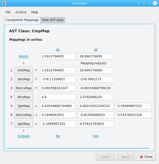
Viewing the raw AST data: Click on the "Raw AST data" tab to see a
full description of the Mapping in the form created by the AST
astDump method.
Component Mappings: If the Mapping is a compound Mapping made up of other Mappings in series or parallel, a tab labelled "Component Mappings" will be visible, and will show the component Mappings expanded into a vertical list that are applied in series or in parallel. Each component Mapping will be represented by a button that can be clicked to see details of the corresponding invididual Mapping. There will also be a set of text boxes into which numerical axis values can be entered (the string "BAD" can also be entered).
For a series CmpMap, the forward transformation of the compound
Mapping will proceeed from the top of the list to the bottom. There will
be a row of text boxes to the
right of the Mapping's button, displaying the Mapping's output axis
values. There will also be an initial row of text boxes, displaying the
axis values supplied as input to the first Mapping in the series. New
values can be entered into any of these boxes - pressing the
Return key (or shifting focus to another box) will cause the
new values to be transformed to re-populate all the other boxes. If new
input values are supplied for the initial component Mappings, the forward
transformation of each Mapping will be used to generate the new values.
If new output values are supplied for the final component Mappings, the
inverse transformation of each Mapping will be used to generate the new values.
If new output values are supplied for an intermediate Mapping, the
forward transformation of subsequent Mappings will be used to generate
later values, and the inverse transformation of earlier Mappings will be
used to generate earlier values. The direction of the transformation used
for each Mapping is indicated by a small vertical arrow to the right of
the Mapping's button (the Mapping for which new output values were
entered will have no arrow, indicating that the user enterd the values).
The tool tips associated with these arrows give more detail.
For a parallel CmpMap, the forward transformation of the compound Mapping will proceeed from the left to the right. Component Mappings that transform lower numbered axes will be at the bottom of the vertical list of Mappings, and axis number will increase verically upwards. See the example below:
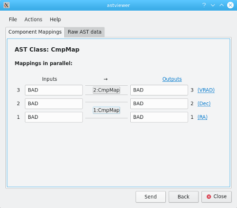
Again, entering numerical axis values into any text box and pressing
Return will cause the other text boxes to be populated with
the corresponding values generated by the appropriate transformations.
The arrow at the middle of the top row indicates the direction of te
transformation that was last used.
Atomic Mappings,(i.e. Mappings that are not made up of other Mappings) will be displayed in the style of a parallel CmpMap, but the Mapping button will be replaced by a simple label indicating ther class of the atomic Mapping.
The Back button: is disabled unless the Mapping details
were displayed as a result of clicking on a Mapping button within a previously
displayed Mapping. If clicked, the currently visible Mapping details will be
replaced by the details of the previously displayed Mapping.
The Send button: performs the same function as the
Back button, except that the currently visible output axis values
are sent back to the previous Mapping and will appear in the appropriate
places when the Mapping details are displayed (new values for all other
text boxes will be regenerated on the basis of the sent axis values).
Frame information describing the inputs or outputs of individual Mapping may be available if the Mapping inputs or outputs correspond to one of the Frames in the displayed FrameSet. In such cases, the Mappings dialog will contain blue hyperlinks that can be clicked to see corresponding Frame information, as described above. The text of these links will be either "inputs", "outputs", or the symbol associated with a specific Frame axis.